Recommendation points
- Where to begin
- How to create a sketch
- Straight equilateral slope
- “Broken” slope
- Selection of rafter cross-section and unification
- Calculation of the pitch of roof trusses
- Mauerlat calculation
- Total count
This article provides a simplified method for calculating the rafter system. You will learn how to quickly and correctly make a decision on the cross-section of the rafters and the width of the span. The adapted mathematical calculation contains a minimum of formulas and leads to fairly accurate results.
There is a standard method for calculating the rafter structure, brought in accordance with SNiP 2.01.07–85 “Loads and Impacts”. It includes many rather complex calculations and reference values. A popular service of sites – online calculation of the gable roof rafter system – will allow you to determine the amount of material very accurately.
Note.The article discusses the methodology for calculating the rafter system of a gable roof with a hip, half-hip or pediment without additional structural elements – canopies, birdhouses, towers, etc. and a slope angle of at least 45 °.
Where to begin
The traditional method assumes the following approach: the roof structure and the cross-section of the beams are selected for the design load. This does not fully meet the requirements of today and the initial data in our case will be the following indicators:
- Requirements (wishes) for the roof structure. First of all, this means the presence of an attic (residential) floor, the location of dormer windows or the presence of an attic technical room.
- The existing dimensions of the house, or the boundaries of the building. 70% of private houses are located in relatively dense buildings, and this should also be taken into account when designing a roof. The limited area of the site and the possible requirements of neighbors for sunlight can make their own adjustments.
- Unification. The rafter system is a multi-piece structure. It is reasonable to try to bring the maximum number of elements to one standard – the section of the board or timber.
The most difficult, oddly enough, is the first point. However, after you have obtained a complete understanding of what functions the rafter system should perform (direct or combined), you can proceed to the design stage.
How to create a sketch
This stage is one of the decisive ones, since in it we learn the approximate sizes of the elements. The main one – the truss truss – will become the basis for further calculations. The drawing itself will be based on two initial parameters:
- Span between load-bearing walls. It is highly desirable that the support points of the rafter system, which transmit vertical loads, are located along the axes of the bearing walls or supports. The distance from the projection of the ridge to the wall is called a half span..
- Ridge height from floor. This parameter is made up of the functional features of the design – the height of the ceiling of the attic, accessible attic or “blank” attic space.
As you know, 75% of simple rafter systems are roofs with a straight and “broken” slope. This significantly affects the calculations, so we will immediately separate these types. Since any standard roof is based on a triangular structure, we will try to limit ourselves to one formula (Pythagorean theorem):
- from2 = a2 + b2
At this stage, you can fairly accurately calculate the area of the slopes and the consumption of roofing material along with the lathing. To do this, it is enough to use the calculation of the gable roof rafter system online, which is provided by many sites.
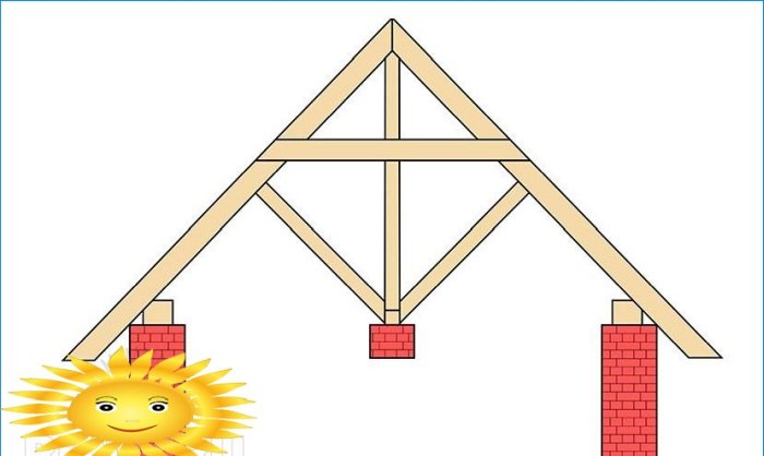
Straight equilateral slope
We transfer to the sketch the dimensions of the floor or the location of the load-bearing walls (the structure does not always imply the presence of a wooden floor) to scale. Then we mark the ridge point and draw straight lines to the walls, taking into account the accepted roof overhang. These straight lines can already be measured and multiplied by the scale – we get the length of the rafter leg.
In accordance with the chosen structure of the organization of the internal space (combined or divided), we place the rafter (crossbar) and determine its length. We place stops, slopes and vertical posts on the drawing, observing the requirements that the portal gave in the article “Do-it-yourself gable roof rafter system.” The spans should not be more than 2 m, and the rafters must have an intermediate brace. In this case, it is enough to adhere to the approximate tolerance framework.
Using the formula for the ratio of the sides of a right-angled triangle, you can calculate any of the dimensions of the truss. The rest of the dimensions can be removed from the drawing through the scale. The main task is to get the dimensions of each of the elements..
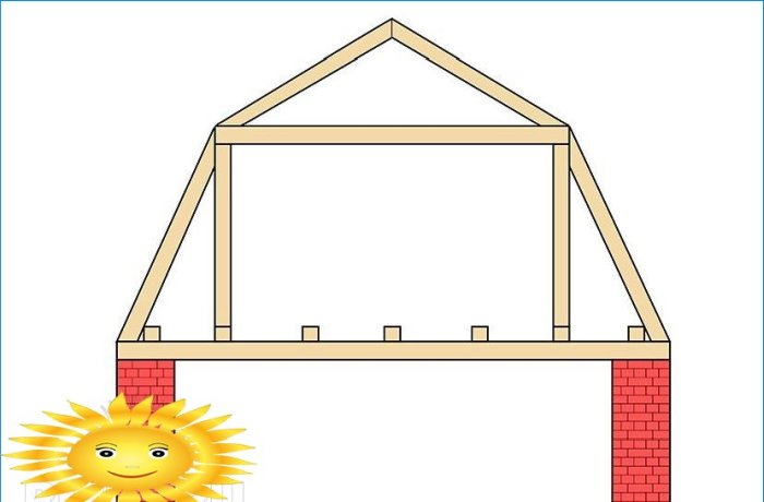
“Broken” slope
This type of roof is always taken in connection with the construction of the attic or the superstructure of the residential floor. It has one characteristic feature – a row of vertical posts at the intersection of the slopes and a rafter bar, which can be located both at the top of these posts and under the ridge. Rows of posts and crossbars form the walls and ceiling of the attic room.
In the same way, we transfer the main elements to the drawing – first the walls and the ceiling, then a series of racks and crossbars (at the ceiling level), then we connect them with lines that will quite accurately show the shape of the break of the slopes.
After measurements and calculations, the lengths of all elements of the truss truss should be added up and 10% added to the resulting number. This will be the total length of the construct of one truss (ODK1).
Selection of rafter cross-section and unification
The section of the system elements, especially the rafter legs, directly depends on the span between the supports in the central part. Of all lumber, timber and board are suitable for the rafter system (not counting the factory glued trusses). At the same time, the board has a much better indicator of the ratio of section to bending strength. In our case, we are talking about the reliability of the rafters, for which the board is used, because there is a margin of depth of the bosom for laying insulation.
Table of dependence of span width and rafter thickness
Span width without intermediate supports, mm Cross-section of the rafter board, mm 2000 to 2500 40×150 2500 to 3500 50×150 3500 to 4000 60×150-180 4000 to 5000 75×180-200 5000 to 6000 100×180-250 It is not recommended to arrange roof trusses of more than 6 meters without intermediate supports.
Advice.When splicing two boards to create a vertical support, place 25 mm (“bosses”) between them at the points of attachment of the trimming boards in increments of 300-400 mm. So the strength of the support will be higher compared to direct splicing..
After determining the sufficient section of the board, you can calculate the volume of one truss. To do this, we multiply the ODK-1 by the sectional area of the board. The resulting volume of one farm (OF1) will be used when calculating the total volume.
Calculation of the pitch of roof trusses
The pitch of the rafters of the attic rafter system depends on the thickness and design of the trusses.
Pitch versus thickness table
Thickness, mm Maximum allowable pitch, mm 40 500 50 600 60 800 75 1000 one hundred 1200 Dividing the length of the longitudinal (parallel to the ridge) wall by the selected step, we get the number of trusses (N). Accordingly, we can calculate the length of the board for the trusses:
- UEC1 x N
truss board volume:
- OF1 x N or UEC1 x Sboard sections x N
Mauerlat calculation
If the rafter system is arranged on a wooden floor, then the entire horizontal strapping refers to it. We will consider the option with a Mauerlat on a stone wall.
Since the uprights, struts and purlins are included in the truss calculation, all that remains is to calculate the horizontal strapping. There is a simple rule here – it must be at least a double rafter leg thick. If the total mass of the roof (together with the battens and roofing material and snow) is noticeably high, three plank layers should be applied.
The volume of the board for the Mauerlat will be equal to the length of the bearing walls multiplied by the section of the board and the number of layers. Mauerlat made of several layers will bond better in corners.
Total count
We put all the resulting volumes together and add 20% for waste and trimming. The number of metal products and fasteners is determined individually. It is only known for certain that the more, the better..
Note.All the given values and proportions of dependence are taken from the normative and reference literature..
Despite the apparent simplicity, this adapted calculation can compete exactly with the online rafter system calculators. However, the decisive word always remains with the one who will carry out the project..

Can you please provide more details or instructions on how to calculate the rafter system based on the given sketch? Specifically, what measurements or formulas should be used?