Recommendation points
- Foundation depth
- Calculation of strip foundations by formulas
- Loads and impacts
- Determination of sole width
- Calculation of strip foundations according to the schedule
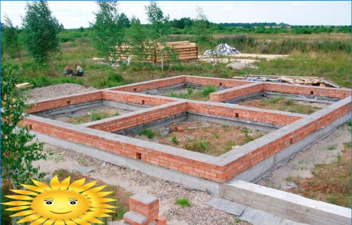
The foundation is the structure of the building below the floor plan. Its purpose is to transfer the loads from the entire structure to the soil foundation. Loaded soil can change its structure, causing deformations in buildings, the limit of which is limited by norms. Correctly made calculation of foundations will ensure the durability and reliability of any building.
The foundations, according to their ability to resist loads, can be divided into rigid and flexible. Structures made of rubble concrete and concrete are rigid. They resist compression well and do not perform well in stretching and bending..
Reinforced concrete foundations have reinforcement inside the structure. It perceives tensile and bending forces, therefore, reinforced concrete is applicable for flexible elements.
Important! A prerequisite for calculating any foundations is the availability of the results of geological and topographic surveys at the construction site.
The building and subgrade are considered to be working together in the calculation. The unfavorable influence of environmental factors can also change the subgrade. For example, temperature affects the properties of swelling and heaving soils, and water can change the structure of subsidence and saline soils..
The level of the location of water in the ground, its possible change, the chemical composition of the water also determine the choice of material, structure and method of building the foundation. All these data are indicated in the survey report.
Foundation depth
When determining the level of the basement sole, the following is taken into account:
- building structure and its purpose;
- the presence of adjacent structures and the mark of the bottom of their foundations;
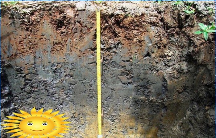
- soil properties;
- ground waters and changes in their position;
- depth of soil freezing;
- adverse effects of the environment;
The elevation of the bottom of the foundation is taken regardless of the level of freezing of the soil, if the foundation is non-porous soil, and the building is heated in winter. Also, if studies and calculations show that there are no deformations that violate the strength of the entire building, with periodic freezing and thawing of the soil.
The foundation of the heated rooms under the outer walls is laid to a depth greater than the calculated value of the depth of freezing of the soil, if the basis for them is heaving soil.
The calculated value of this depth is found by the formula:
df = kh* dfn, Where
- kh – coefficient of thermal conditions in the building;
- dfn – standard depth of soil freezing.
For buildings that are not heated in winter kh= 1.1; for heated kh taken according to the table.
Building type Air temperature in adjoining room 0 five ten 15 20 and more Ground floors 0.9 0.8 0.7 0.6 0.5 Lag floors 1.0 0.9 0.8 0.7 0.6 Insulated floors 1.0 1.0 0.9 0.8 0.7 Basement building 0.8 0.7 0.6 0.5 0,4 Standard value dfn taken as the average value of the maximum annual seasonal freezing depths for 10 years.
This value can be calculated using the formula:
Mt– a dimensionless number equal to the sum of the absolute values of temperatures below zero in winter in a particular area. It is found in SP 131.13330.2012.
d0 accepted:
- 0.23 – clays and loams;
- 0.28 – silty and fine-grained sands;
- 0.3 – coarse and medium-grained sands;
- 0.34 – coarse soils.
The heaving soils include:
- clay-containing;
- fine-grained and silty sands;
- coarse-grained with clay-silty inclusions.
Calculation of strip foundations by formulas
The calculation of the foundations of buildings is done according to 2 groups of limit states:
- bearing capacity – the first group;
- deformations – the second group.
The first limiting state implies a complete impossibility to operate the building. The second is when normal operation is difficult. The calculation is performed to determine the optimal dimensions of the foundation structure.
Loads and impacts
Standard load multiplied by safety factor (overload) – ?f, gives the value of the calculated.
Design Reliability factor ?f Metal 1.05 Concrete, density >1600 kg / m3 1.10 Reinforced concrete, stone, reinforced stone, wooden, density <1600 kg / m3: prefabricated – 1,2 at the construction site – 1.3 Soils natural 1.1 bulk 1.15 For snow and wind load ?f = 1.4, for temperature action ?f = 1.1.
By the amount of time of action, the loads are divided into permanent and temporary. During construction, as well as in operation, constant loads operate without interruption. These include the weight of all building structures and the weight of the soil. Temporary loads are divided into:
- long-term operation (temporarily located equipment, storage of materials and parts of any production, weight of people and animals, overhead and bridge cranes);
- short-term action (snow, wind, ice, commissioning and repair equipment, people, etc.);
- special action (from explosion, accidents, equipment breakdown, changes in the structure of the base, etc.).
The calculation uses a combination of loads:
- Basic – permanent + long-acting + short-acting.
- Special – permanent + long-term + short-term + one special action.
When calculating the base by deformations, the basic combination of loads is used. The main combination is also taken for strength in the calculation, but if there are special loads, the calculation is carried out for a special combination. For a certain type of load combination, the reduction factors of the combination are taken into account in the calculation – ?.
Ultimately, a more dangerous combination of loads is chosen. For residential buildings with a rigid structure, the load on the foundation consists of the weight:
- Constant loads:
- Walls, intermediate floors, basement floors (if any).
- Foundation and weight on its ground benches.
- Temporary loads:
- Snow.
A uniformly distributed standard load for residential buildings can be taken according to SNiP – 1.5 kPa (overload coefficient – ?f = 1.3).
Determination of sole width
Foundations of residential buildings with a rigid structure scheme are calculated as centrally compressed. They are arranged symmetrically with respect to the floor or basement wall. The calculation is made based on the condition of the limiting balance of all forces affecting the foundation.
F – full load on the foundation, h – foundation depth b – foundation base width
To make a preliminary calculation, you can use the R value0 according to the tables below.
Priming Soil density, kg / cm2 Internal friction angle ? Deformation modulus E, kg / cm2 Volumetric weight?, T / m3 dense medium density Large sands 4.5 3.5 36-41 2000-500 1.75-1.85 Medium sands 3.5 2.5 33-38 500-300 1.6-1.9 Fine sands: 30-36 400-250 – low moisture 3.0 2.0 1.6-1.9 – saturated with water 2.5 1.5 1.8-1.9 Dusty sands: 28-34 250-125 1.8-2.0 – low moisture 2.5 2.0 – wet 2.0 1.5 – water-saturated 1.5 1.0
Priming Porosity coefficient Soil consistency in kg / cm2 Internal friction angle ? Deformation modulus E, kg / cm2 Volumetric weight?, T / m3 dense plastic Sandy loam 0.5 3.0 3.0 18-28 200-125 1.7-1.95 0.7 2.5 2.0 1.5-1.85 Loam 0.5 3.0 2.5 12-25 250-80 1.8-1.95 0.7 2.5 1.8 1.75-1.9 1.0 2.0 1.0 1.7-1.8 Clays 0.5 6.0 4.0 30-36 400-250 1.9-2.0 0.6 5.0 3.0 1.9-2.0 0.8 3.0 2.0 1.8-1.9 1.1 2.5 1.0 1.7-1.8 For a solid strip foundation, the width of the sole is determined:
- F is the load acting on the upper part of the foundation;
- R0 – soil resistance, which is taken from the tables;
- ?mt– the average specific gravity of the foundation and soil on its edges;
- h – foundation height.
For example, let us determine the width of the sole of a solid strip foundation with a rigid scheme with the following data:
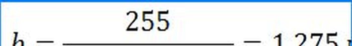
- F = 255 kN;
- R0 = 250 kPa – for loam with a porosity coefficient of 0.7;
- Laying depth – 1.8 m, height h = 2.0 m. Foundation material – concrete M 200, ?mt= 2.0 kg / m3.
For depths less than 1.5 m, coefficient m is applied.
Laying depth h 1.4 1.3 1,2 1.1 1.0 0.9 0.8 0.7 0.6 Coefficient m 0.97 0.93 0.90 0.87 0.83 0.80 0.77 0.73 0.70 The required sole width is obtained:
Next, we clarify R0 for a foundation base depth of less than 2.0 m using the formula:
R = R0* [1 + k1 (b – b0) / b0] * (d + d0) / 2d0;
- k1 – for clays, loams, sandy loams and silty sands – 0.05; for coarse sands and coarse soils – 0.125.
- b and d – width and depth of the foundation
- b0 and d0 – values of width and depth accepted in tables
R = 250 • [1 + 0.05 (1.2 – 1) / 1] • (1.8 + 2) / 2 • 2 = 240 kPa
We specify the width of the base of the foundation
To obtain more accurate data, the calculated value of soil resistance is calculated from survey data.
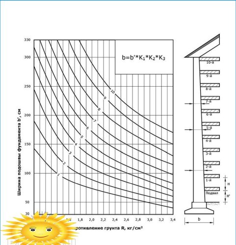
Calculation of strip foundations according to the schedule
Calculation schedule for solid strip foundations for external brick walls
H 390 360 330 270 k1 1.04 1.00 0.96 0.90
? 0.0 five% ten% 15% 20% 25% thirty% k2 1.07 1.04 1.02 1.00 0.98 0.96 0.93
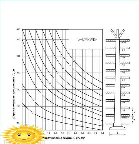
R 0.00 300 600 900 1200 1500 1800 2100 k3 0.76 0.81 0.86 0.90 0.95 1.00 1.05 1.10 Schedule for the calculation of solid strip foundations for internal walls
H 390 360 330 270 k1 1.04 1.00 0.96 0.90
R 0.00 500 1000 1500 2000 2500 3000 3500 k3 0.52 0.62 0.72 0.82 0.91 1.00 1.09 1.18 According to the schedule created for civil buildings with brick walls, the calculation is made using the R data and the number of floors. The found sole width is multiplied by the correction factors k1, to2, to3:
- to1 – takes into account the height of the floor;
- to2 – ratio of window area to wall area in%;
- to3 – the load transmitted by the overlap of one floor.
It is possible to determine the width of the sole using the graph only if the wall thickness indicated on the graph coincides with the accepted thickness of the brickwork.
For example, let us find the width of the basement basement of an external brick wall 77 cm thick in a three-storey house (with a basement). In this case, R = 2.0 kg / cm2; H = 3.0 m; ? = 20%; P = 1800 kg / running. m. According to the graph, we find that the width of the sole is b ’= 110 cm; b = 110 • 0.98 • 1.5 = 113 cm.
All tables and graphs provided are indicative only. A more accurate calculation is made by specialists based on soil studies (field and laboratory) at the construction site.


Can you provide any step-by-step guidance or formulas for accurately calculating the foundation for a construction project?
Can you please provide a step-by-step guide on how to accurately calculate the foundation for a construction project?