Recommendation points
- What you need to know about fittings
- Reinforcement consumption for different types of foundations
- Calculation of reinforcement for slab foundation
- Calculation of reinforcement strip foundation
- Consumption of metal elements for a columnar foundation
- Methods and techniques for connecting reinforcement
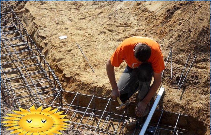
For correct reinforcement of the foundation of a private house, it is necessary to calculate the reinforcement, its competent laying and knitting. Incorrect calculation will lead to damage to the foundation or to unnecessary costs. We will discuss the reinforcement of foundations of various structures and the principle of calculating steel reinforcement, accompanied by diagrams and pivot tables.
Reinforcement of the foundation requires the study of the structure of the frame made of reinforcement, the selection and calculation of the cross-section, length and mass of the profile steel. Insufficiency of reinforcement leads to a decrease in strength and a possible violation of the integrity of the building, and its overabundance leads to unreasonably high costs at this stage.
What you need to know about fittings
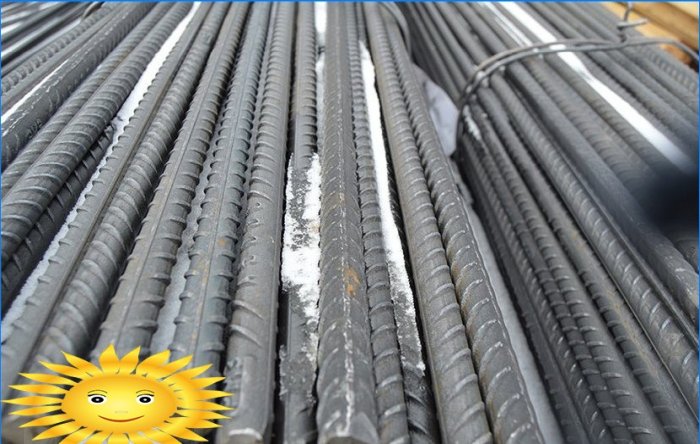
When reinforcing a concrete base, two types of construction reinforcement are used:
- class A-I – smooth;
- class A-III – ribbed.
Smooth reinforcement is used in non-stressed areas. It only forms the frame. Ribbed reinforcement, due to its developed surface, provides better adhesion to concrete. Such rods are used to compensate for the load. Therefore, the diameter of such reinforcement, as a rule, is larger than that of a smooth one, within the same foundation..
The diameter of the bar depends on the type of soil and the mass of the structure.
Table No. 1. Minimum standard diameters of valves
Location and operating conditions Minimum size Normative document Longitudinal reinforcement, no more than 3 m long O 10 mm Appendix No. 1 to the design manual “Reinforcement of elements of monolithic reinforced concrete buildings”, M. 2007 Longitudinal reinforcement, longer than 3 m O 12 mm Appendix No. 1 to the design manual “Reinforcement of elements of monolithic reinforced concrete buildings”, M. 2007 Structural reinforcement in beams and slabs over 700 mm high Sectional area not less than 0.1% of the concrete sectional area “Guidelines for the design of concrete and reinforced concrete structures from heavy concrete (without prestressing)”, M., Stroyizdat, 1978 Transverse reinforcement (clamps) in knitted frames of eccentrically compressed elements Not less than 0.25 of the largest diameter of the longitudinal reinforcement and not less than 6 mm “Concrete and reinforced concrete structures without prestressing reinforcement” SP 52-101-2003 Transverse reinforcement (clamps) in knitted frames of bending elements O 6 mm “Concrete and reinforced concrete structures without prestressing reinforcement” SP 52-101-2003 Transverse reinforcement (clamps) in knitted frames of bending elements at a height less than 0.8 m O 6 mm “Guidelines for the design of concrete and reinforced concrete structures from heavy concrete (without prestressing)”, M., Stroyizdat, 1978 more than 0.8 m O 8 mm If it is planned to build a wooden one-story building on dense ground, tabular values of the reinforcement diameters can be taken. If the house is massive, and the soil is heaving, the diameters of the longitudinal reinforcement are taken in the range of 12-16 mm, in exceptional cases – up to 20 mm.
In the calculations, you will need information about reinforcement from GOST-2590-2006.
Table No. 2
Rolled steel diameter, mm Cross-sectional area, cm2 Specific theoretical weight, kg / m Specific length, m / t 6 0.283 0.222 4504.50 8 0.503 0.395 2531.65 ten 0.785 0.617 1620.75 12 1.131 0.888 1126.13 fourteen 1,540 1,210 826.45 sixteen 2,010 1,580 632.91 18 2,540 2,000 500.00 20 3.140 2,470 404.86 22 3,800 2.980 335.57 Reinforcement consumption for different types of foundations
Foundations of different design differ in the area over which the load from the structure is distributed. For each type, the calculation of the number of reinforcement is carried out according to its requirements. For a correct comparison, the calculation of all foundations will be carried out for the following house sizes:
- width – 6 m;
- length – 8 m;
- length of load-bearing walls – 14 m.
Calculation of reinforcement for slab foundation
This is the most material-intensive type of foundations. In concrete, there are two levels of reinforcing gratings located 50 mm below the upper and above the lower border of the slab. The laying step depends on the perceived loads. For houses made of stone / brick, the frame cell is usually 200×200 mm. At the points of intersection of the reinforcement, the upper and lower levels of the frame are connected by vertically arranged bars.
Reinforcing frame of slab foundation
Let’s calculate the reinforcement for our reference house (see above).
1. Horizontal reinforcement, Ø 14 mm, corrugated.
- 8000 mm / 200 mm + 1 = 41 pcs. length 6 m.
- 6000 mm / 200 mm + 1 = 31 pcs. length 8 m.
- Total: (41 pieces x 6 m + 31 pieces x 8 m) x 2 = 988 m – for both levels.
- Weight 1 linear m of rod O 14 mm – 1.21 kg.
- Total weight – 1195.5 kg.
2. Vertical reinforcement, Ø 8 mm, smooth. For a slab thickness of 200 mm, the bar length will be 100 mm.
- Number of crossings of horizontal reinforcement: 31 х 41 = 1271 pcs.
- Total length: 0.1 mx 1271 pcs. = 127.1 m.
- Weight: 127.1 mx 0.395 kg / m = 50.2 kg.
3. Heat-treated wire Ø 1.2–1.4 mm is usually used as knitting wire. Since the place of one joint, as a rule, is tied up two times – first when laying horizontal rods, then vertical ones, the total amount of wire is doubled. One connection requires approximately 0.3 m of thin wire.
- 1271 pcs. x 2 x 0.3 m = 762.6 m.
- Specific weight of wire O 1.4 mm – 12.078 g / m.
- Wire weight: (762.6 mx 12.078 g / m) / 1000 = 9.21 kg.
Since a thin wire can break / get lost, you need to purchase it with a margin.
The total amount of materials for reinforcing the slab frame is given in table No. 3.
Table No. 3
Diameter, mm Estimated length, m (without stock) Estimated weight, kg (without stock) fourteen 988 1 195.5 8 127.1 50.2 1.4 381.3 9.2 TOTAL: 1,254.9 Calculation of reinforcement strip foundation
The strip foundations are reinforced concrete beams located under all load-bearing walls. It contains straight sections, corners and tees. The calculation is performed for straight sections with a small margin for corner reinforcement. We accept tape width – 400 mm, depth – 700 mm.
Schematic representation of a straight section of a strip foundation
The junction of the load-bearing inner and outer walls
Outside or inside corner of outside walls
Reinforcement of strip foundations is also two-level. For longitudinal sections, a bar of class A-III is used, and for vertical and transverse (clamps) – a bar of class A-I. The section of reinforcement is taken for strip foundations slightly lower than for slab foundations, under the same construction conditions.
Let’s calculate the reinforcement for the reference building selected as an example (see above).
1. Horizontal longitudinal reinforcement, Ø 12 mm, grooved. For a tape width of 400 mm, it is sufficient to lay two rods in each of the two levels. For a wider tape, lay 3 rods.
- Length of all belts: (8 m + 6 m) x 2 + 14 m = 42 m.
- Rebar total length: 42 mx 4 = 168 m.
- Reinforcement weight: 168 mx 0.888 kg = 149.2 kg.
- Taking into account the strengthening of the corners, the mass of the rods will be 160 kg.
2. Vertical reinforcement Ø 8 mm, smooth. For a belt depth of 700 mm, the bar length is 600 mm. The distance between the vertical bars along the length of the tape is taken as 500 mm.
- Number of rods: 42 m / 0.5 + 1 = 85 pcs.
- Total length of rods: 85 pcs. x 0.6 m = 51 m.
- Bar weight: 51 mx 0.395 kg / m = 20.1 kg.
3. Horizontal transverse (clamp) reinforcement Ø 6 mm, smooth. For a tape width of 400 mm, the bar length is 300 mm. The distance between the transverse bars along the length of the tape is taken as 500 mm.
- Number of rods: 42 m / 0.5 + 1 = 85 pcs.
- Total length of rods: 85 pcs. x 0.3 m = 25.5 m.
- Bar weight: 25.5 mx 0.222 kg / m = 5.7 kg.
4. Knitting wire. Calculation when tying each connection with one wire Ø 1.4 mm:
- Number of nodes: 85 х 4 = 340 pcs.
- Total length: 340pcs x 0.3 m = 102 m.
- Total weight: (102 mx 12.078 g / m) / 1000 = 1.23 kg.
- When knots are knitted in two times, the weight of the wire will be 2.5 kg.
The total amount of materials for reinforcing the tape frame is given in table No. 4.
Table No. 4
Diameter, mm Estimated length, m (without stock) Estimated weight, kg (without stock) 12 180.2 160 8 51 20.1 6 25.5 5.7 1.4 104 2.5 TOTAL: 188.3 Consumption of metal elements for a columnar foundation
Such a foundation consists of supports, the lower part of which is located below the freezing zone, and a strip foundation resting on them. For a freezing depth of 1.5 m, the height of the pillars is 1300 mm (see Fig.), I.e. their base is 1700 mm below the soil level.
Arrangement of reinforcement in a columnar foundation, side view: 1 – sand cushion; 2 – reinforcement Ø 12 mm; 3 – pile reinforcement
Poles are installed in the corners of the building and along the tape every 2-2.5 m.
Let’s calculate the number of rods for the configuration of the house, taken as an example (see above). To do this, you need to calculate the number of reinforcement for the pillars and add it up with the calculation result for the strip foundation.
Only vertical rods are loaded in the posts, horizontal ones are used to form the frame. A pillar with a diameter of 200 mm is reinforced with four vertical reinforcement. Number of poles: 42 m / 2 m = 21 pcs.
1. Vertical reinforcement Ø 12 mm, grooved.
- Fittings total length: 21 pcs. x 4 pcs. x 1.3 m = 109.28 m.
- Rebar weight: 109.29 mx 0.888 kg = 97.0 kg.
2. Horizontal reinforcement Ø 6 mm, smooth. For dressing, horizontal clamps should be placed at a distance of no more than 0.5 m. For a depth of 1.3 m, three levels of dressing are sufficient. The vertical sections are spaced 100 mm apart. The length of each horizontal segment is 130 mm.
- Total length of horizontal bars: 21 pcs. x 3 pcs. x 4 pcs. x 0.13 m = 32.76 m.
- Bar weight: 32.76 mx 0.222 kg / m = 7.3 kg.
3. Knitting wire. Each post contains three levels of horizontal rods, which tie four vertical.
- Length of knitting wire per pole: 3 pcs. x 4 pcs. x 0.3 m = 3.6 m.
- Wire length for all poles: 3.6 mx 21 pcs. = 75.6 m.
- Total weight: (75.6 mx 12.078 g / m) / 1000 = 0.9 kg.
The total amount of materials for reinforcing the columnar foundation, taking into account the tape frame, is given in table No. 5.
Table No. 5
Diameter, mm Estimated length, m (without stock) Estimated weight, kg (without stock) 12 289.49 257 8 51 20.1 6 58.3 12.9 1.4 179.6 3.4 TOTAL: 293.4 Methods and techniques for connecting reinforcement
To connect the crossing rods, welding and wire knitting are used. For foundations, welding is not the best method of installation, as it weakens the structure due to the violation of structural integrity and the risk of corrosion. Therefore, as a rule, the reinforced frame is “knitted”.
This can be done by hand with pliers or hooks, or with a special gun. With the help of pliers, unannealed large diameter wire is knitted.
Techniques for manual knitting of reinforcement using pliers: 1 – knitting with wire in bundles without pulling up; 2 – knitting corner knots; 3 – two-row knot; 4 – cross knot; 5 – dead node; 6 – fastening the rods with a connecting element; 7 – rods; 8 – connecting element; 9 is a front view; 10 – rear view
For thin annealed wire, it is more convenient to use hooks: simple or screw.
Video: A visual lesson in knitting reinforcement with a homemade crochet
Knitting gun
For large volumes of work, use a knitting gun. At the same time, the mating speed is much higher than traditional methods, but there is a dependence on the power source. In addition, it is for foundations that the gun cannot be used everywhere – some areas are difficult for it to access..
Can you please explain in more detail how the reinforcement of the foundation is calculated, and what are the processes involved in laying and knitting the reinforcement?